Time-Resolved, Multi-frame X-Ray Imaging of Laser-Produced Plasmas
L.A.Gizzi, A.Giulietti, O.Willi*
Istituto di Fisica Atomica e Molecolare del CNR, Pisa, Italy
*Imperial College of Science, Technology and Medicine,
London, England
ABSTRACT
A novel X-ray imaging system based on a microchannel-plate combined
with a multi-pin-hole camera has been employed to study X-ray emission
from laser-produced plasmas in the 0.5 - 3 keV photon energy range. In
particular, the interaction of intense laser radiation with such plasmas,
in conditions relevant to inertial confinement fusion, was monitored by
recording a sequence of consecutive X-ray images with a temporal resolution
of 140 ps and a spatial resolution of 10 um. These images provide valuable
information on the main physical mechanisms involved in the interaction
process, including collisional absorption of the incident laser energy
and electron thermal conduction.
1. INTRODUCTION
The study of plasma self-emission in the X-ray region is widely regarded
as a primary tool for the characterisation of hot, dense plasmas generated
in laser-matter interaction processes. Indeed, in the case of experiments
designed to investigate laser-plasma coupling processes or hydrodynamic
laser induced instabilities in the interaction with preformed plasmas,
a detailed analysis of the spectral and spatial features of the X-ray emission
allows a direct monitoring of the modifications induced by the interaction
processes on plasma conditions[1].
On the other hand, X-ray imaging with high temporal resolution is also
considered the key diagnostic technique to study the overall dynamics and
the evolution of distortions in the implosion of inertial confinement fusion
capsules[2].
Due to the strong X-ray emissivity of laser produced plasmas, a simple
imaging device consisting of a pin-hole camera (PHC) can be employed to
obtain X-ray images of the plasma. Both magnification and resolution of
such a device can be easily calculated from simple geometrical consideration.
The image thus obtained can be recorded directly by using X-ray sensitive
detectors (windowless CCD cameras, X-ray films) or by employing phosphor
screens coupled to optical image intensifiers. Presently available intensifiers
based on the microchannel-plate[3]
(MCP) technology can easily provide a thousand-fold overall gain in intensity.
Ordinary CCD cameras or commercial photographic B&W film can then be
used to record the intensified image.
Temporal resolution can be achieved by forming the X-ray image generated
by the PHC on a position sensitive time resolving device. By using an X-ray
streak camera, temporal resolution up to the picosecond range can be obtained.
However the spatial information is restricted to the direction perpendicular
to the streak direction (1-D time-resolved imaging). This technique has
been successfully employed for several years[4]
and is very useful when a continuous mapping of the temporal evolution
is required. However, two-dimensional position sensitive devices with a
temporal resolution as high as a few tens of picosecond based on microchannel-plates
(MCP)[5]
can now be employed. MCP's are characterised by a very low capacitance
that enables fast switching of the externally applied electric fields.
These devices can therefore be used as
gated intensifiers as well
as a DC intensifiers and usually do not require additional intensifiers
due to their intrinsic high gain.
In all the applications considered above, in order to avoid motional
blurring of the images, framing times as short as few tens of picoseconds[6]
are often necessary. On the other hand, the scalelength of the features
of interest can be as small as few microns, thus accounting for the need
of high spatial resolutions. Furthermore, another important feature of
such imaging systems is the number of frames that can be recorded on a
single interaction event, so that the temporal evolution can be mapped
with sufficient accuracy. The final configuration is therefore a trade-off
between scientific requirements, spatial, temporal and spectral accuracy
on one side, and flexibility, reliability, and ease of use on the other
side.
In this paper we describe the implementation of multi-frame X-ray
imaging with high temporal resolution for the study of laser interaction
with preformed plasmas. A detailed description of the technique will be
given here with emphasis on its application to the investigation of laser-plasma
coupling processes. The interaction of a high intensity laser pulse with
preformed plasmas, generated by laser heating of thin Al foils, was investigated
by means of this diagnostic, in conditions of temperature, density and
laser intensity typical of Inertial Confinement Fusion experiments.
2. IMAGING TECHNIQUE
An X-ray detection unit based on MCP, in the following referred to as SLIX
(Strip Line Imager for X-rays), was designed[7]
to enable four-frame X-ray imaging with 140 ps gate-time and inter-frame
time adjustable from zero to a few nanoseconds. A diagram of the SLIX
sensitive unit is shown in Fig.1. The input surface of the microchannel-plate
detector was coated with a 500 nm copper layer in four separated rectangular
regions (Strip-Lines) acting as photocathodes while the output surface
was uniformly coated with a thin copper layer. Each strip-line could be
activated independently by a high voltage pulse. Photons incident on one
of the activated strip-lines generates photoelectrons that, accelerated
by the external electric field, hit the walls of the micro-channel producing
secondary electron emission. This process takes place several times during
the flight of the electrons in the micro-channel resulting in a photomultiplier-like
gain. The electrons produced are finally driven onto a phosphor screen
by a second electric field. Due to the small electron path lengths
(see Fig.1), a relatively large electric field is capable of preserving
the spatial distribution of the outcoming electrons. A standard B&W
film records the light produced by the phosphor screen and collected by
a fibre optic bundle plate.
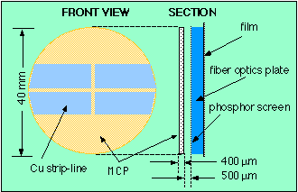
Fig.1 Schematic arrangement of the Strip-Line X-ray Imager detection
system with the MCP input surface showing the four 500 nm thick Cu coated
regions. (Kentech Instr. Ltd., UK)
A specifically designed PHC equipped with a 4-pin-hole array capable of
producing four identical images of the object plasma onto the four sensitive
strip-lines of the MCP was employed as schematically shown in Fig.2. The
4-pin-hole array was made by piercing the four pin-holes on a 30 um thick
Platinum foil using a Q-switched 40 ns Nd laser beam focused onto the foil
by a microscope objective. The PHC magnification in the final set-up used
for the experiment described below was 13X with a pin-hole size of 10 um.
Both magnification and pin-hole size were chosen in order to resolve details
of about 10 um in the plasma. Since the intrinsic SLIX spatial resolution,
determined by the MCP structure, is about 100 um, the 13X image magnification
allows the limit resolution (10 um) of the PHC imaging system, set by the
pin-hole diameter, to be attained.
3. SPECTRAL X-RAY SELECTION
In our experiment the time-resolved imaging was mainly devoted to investigate
modifications of plasma condition induced by local energy deposition. Such
modifications occur on a time-scale short compared to the typical time-scale
of relaxation of atomic physics processes. To this purpose continuum emission
is a more sensitive parameter compared to line emission. In fact, continuum
radiation and, in particular, radiation originating from free-free processes,
is closely related to the conditions of the electron population and is
only coupled to the ions via their charge number and the electron-ion collision
frequency. In contrast, the properties of line radiation are strongly related
to the particular equilibrium holding in the plasma, as well as to ion
relaxation processes.

Fig.2. Schematic set-up of the imaging system showing the pin-hole
set arrangement and the input window of the four-frame gated X-ray Imager
SLIX. The geometry of the pin-hole array was defined by the image magnification
in order to produce four images centred on the four sensitive areas of
the detector.
For this reason a 3 um thick Al foil filter was used to block visible radiation
as well as to select the transmitted X-ray spectrum. Fig.3 shows
the transmittivity of the 3 um Al filter in the spectral range of interest
in this study. Also plotted on the same graph is the expected X-ray spectral
emissivity of the plasma calculated by using the atomic physics code RATION[8],
assuming a collisional-radiative equilibrium, for an Al plasma at an electron
density of  and an
electron temperature of 450 eV.

Fig.3. X-ray transmittivity of the 3 um Al filter used in the
SLIX imaging system. The X-ray emissivity of a 450 eV, 1.5x10²⁰
cm-3 Al plasma in collisional-radiative equilibrium is also
plotted for comparison.
These values were chosen according to experimental measurements performed
in similar experimental conditions and described in detail elsewhere[9].
Due to the Al K-shell absorption edge at 1560 eV, most of the line emission
from He-like and H-like Al ions is strongly absorbed by the Al filter.
Therefore the dominant component of the transmitted X-rays will be continuum
radiation originating from free-bound and free-free transitions in He-like
and H-like Al ions, as discussed above.
4. EXPERIMENTAL RESULTS
Plasmas were produced by irradiating targets consisting of a 800 nm thick
Al stripe (300 um wide, 500 um long) coated onto a 0.1 thick um plastic
substrate as shown schematically in Fig.4. Four frequency doubled laser
beams (
 )
of the Vulcan laser at the Central Laser Facility (Rutherford Appleton
Laboratory, Chilton, Didcot, UK) were superimposed on target, two on each
side, in order to generate and heat the plasma. The dashed ellipse around
the Al coating shows schematically the size of the focal spot of the four
heating beams. A fifth infrared laser beam (
 )
was then focused on the target along its longitudinal axis using an f/10
optics, as shown in Fig.4 and was timed to reach the target typically between
2 and 3 ns after the peak of the plasma forming beams.
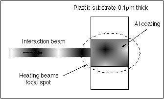
Fig.4 Target configuration and laser beams arrangement for the
production of laser plasmas. The Al coating was either 500nm or 700nm thick.
The Al target was 300um wide and 500um long (along the interaction beam
axis). The preformed plasma is created from the laser-heated exploding
foil and expands perpendicularly to the foil plane .
Fig.5 shows a time integrated pin-hole X-ray image of the target
heated with 600 ps, 0.53 um laser pulses at an intensity of  on each side, obtained with the SLIX working as a DC X-ray intensifier.
The 600 ps interaction pulse was delayed by 2.2 ns with respect to the
heating pulses and was focused on the (left) edge of the foil target at
an intensity was approximately
  ,
in a 140 um (FWHM) focal spot using an
  optics. The shape of the bright X-ray emitting region, even though integrated
in time, clearly matches the shape of the Al heated target as shown in
Fig.4. This observation suggests that most of the X-ray emission occurs
during the plasma start-up phase, before hydrodynamic expansion takes place.
As a consequence, in time integrated images, the effects of the interaction
occurring in the field of view of the Al stripe are masked by the intense
X-ray emission occurring in the early stage of plasma formation. Therefore
temporal resolution is needed when studying interaction effects.
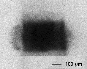
Fig.5 Time integrated X-ray image of a 700 nm thick, 500 um
long, 300 um wide Al target heated on each side by a 600 ps, 0.53 um laser
pulses at an intensity of ~2x10¹³ W/cm2. The 600ps
interaction pulse was delayed by 2.2 ns and was focused on target at an
intensity of approximately 1013 W/cm2. The image
was obtained with the SLIX working as a DC X-ray intensifier.
Temporal resolution can be achieved by the SLIX device when a gate voltage
is applied to each strip-line. A 650 V, 200 ps FWHM pulse was used to generate
an electric field of approximately 15 KV/cm in the MCP, which was added
to a low DC bias voltage (<=300 V). Due to the extremely non-linear
behaviour of the MCP output current with the applied electric field, the
gain produced by the low DC electric field, by itself, is negligible. Nevertheless,
once added to the 200 ps gating pulse, this DC field activates the gain
of the MCP. On the other hand by varying the DC voltage it is possible
to adjust the overall MCP gain. The gate pulse generated by a single pulse
generator was split into four identical pulses which were applied to the
four strip-lines by using high frequency cables. The length of each cable
was varied in order to synchronise the four frames according to the timing
of the laser pulses.
Images like the one shown in Fig.5 were produced on each
of the four frames of the SLIX and then, by driving the frames at different
times, a temporal sequence of four X-ray images of the laser-plasma interaction
region was recorded. The timing of each frame was set according to the
particular configuration of the interaction experiment as shown schematically
in Fig.6. Typically the first frame was synchronised with the heating
laser pulse while the remaining three frames were usually synchronised
at different times during the interaction laser pulse.

Fig.6. Timing of the SLIX frames (1 to 4) relative to the timing
of the laser pulses. The frame#1 was synchronized with the heating (H)
pulse to monitor plasma formation. All the remaining three frames were
synchronized with the interaction (I) pulse.
A sequence of time resolved X-ray images of the laser-plasma interaction
region is shown in Fig.7. The target was heated at an incident laser
intensity of  on
each side, while the intensity of the 600 ps interaction pulse was
  .
As indicated in Fig.6, frame #1 was synchronised with the peak of the 600
ps heating pulse while the remaining three frames (#2, 3 & 4) were
timed consecutively to record the evolution of the interaction process
with the preformed plasma. X-ray emission relative to the heating phase
involves the whole Al target foil and, though very intense in the first
frame, drops below the detection level of the X-ray imaging system in the
following frames, that is, after ~2 ns. This is consistent with the X-ray
time resolved spectra taken in similar experimental conditions and presented
in a previous work[10]
in which a simple model of X-ray emissivity was presented and discussed
to explain the temporal behaviour of experimental X-ray emission.
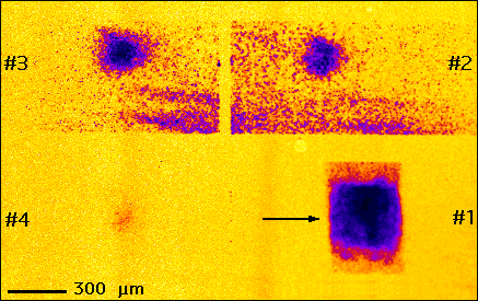
Fig.7 Sequence of time resolved X-ray images of laser interaction
with a preformed plasma produced by irradiation of a 700 nn thick, 300
um wide, 500 um long Al stripe at an intensity of ~ 4x10¹³ W/cm2
on each side. The interaction beam was focused on the left edge of
the plasma, as shown schematically by the arrow, in a 140 um (FWHM) focal
spot at an intensity of 5.8x10¹³ W/cm2. The framing
time was 120 ps, while the first interframe, that is the peak-to-peak delay
between gate #1 and gate #2, was 2.2 ns, as shown in Fig.6. The second
and third interframes were zero and 100 ps respectively. The first frame,
syncronized with the peak of the plasma heating pulse, shows X-ray emission
from the plasma heating phase while the remaining three frames show the
X-ray emission due to the interaction of the delayed laser pulse with the
preformed plasma.
X-ray emission takes place again when the interaction pulse strikes the
preformed plasma. Such an emission is localised in a rather small region,
close to the entrance of the plasma, whose width (i.e. the size in the
direction perpendicular to the direction of propagation of the laser beam
and located in the plane of the target) is approximately 200 um, that is,
comparable with the focal spot size of the interaction beam (140 um FWHM).
On the other hand, the longitudinal size of the emission, once the effect
of the angle of view (45 degrees) between the imaging device and the target
plane is taken into account, varies from 300 um in the frame #2 to approximately
360 um in the frame #3. The emissivity of this region rapidly decreases
in time as shown by the weak image of frame #4 taken at the end of the
laser interaction pulse. These circumstances, which make the interaction
region "visible" in the X-rays, indicate that a strong absorption of laser
energy by the plasma takes place in this small region. According to detailed
numerical simulations7 the plasma electron density in this region
is  , that is, well
below the critical density for the wavelength of the infrared interaction
beam. In addition, the longitudinal density scalelength at the time of
interaction is of the order of 100 um, therefore, propagation of the interacting
beam occurs without strong refraction and/or deflection effects. In these
conditions the main absorption process is the classical collisional absorption,
i.e. inverse bremsstrahlung (IB), and electron heat transport accounts
for propagation of the absorbed energy across the whole plasma. These physical
mechanisms can be investigated by studying the features of X-ray emission
for different plasma and laser conditions as discussed below.
5. PHYSICAL INSIGHTS
It is instructive to discuss briefly some aspects of the physics of laser-plasma
interaction that should be taken into account in the analysis of the X-ray
images presented above. In particular, absorption of laser energy by the
plasma and electron heat transport will be considered as they play a very
important role in determining the observed features of X-ray emission.
5.1 Inverse bremsstrahlung absorption
As already pointed out above, laser energy is transferred to the plasma
mainly via IB absorption. Since most of the X-ray emission detected by
our imaging system originates from electron-ion collision processes (bremsstrahlung
and recombination), we expect strong X-ray emission from the region of
plasma directly heated by the laser electric field, that is, from a region
whose length is comparable with the IB absorption length. In other words,
X-ray emission gives a good indication of the extent of plasma over which
most of the laser energy is absorbed. Indeed, the longitudinal size of
the X-ray emitting region measured from X-ray images was found to be in
good agreement with the IB absorption length calculated for our plasma
conditions assuming  and
and  .
.
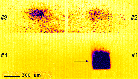
Fig.8 Sequence of time resolved X-ray images of laser interaction
with a preformed plasma. The interaction beam was focused on the left edge
of the plasma, as shown schematically by the arrow, in a 140 um (FWHM)
focal spot at an intensity of 5.8x10¹³ W/cm2. The
framing time was 120 ps, while the first interframe, that is the peak-to-peak
delay between gate #1 and gate #2, was 2.2 ns, as shown in Fig.6. The second
and third interframes were zero and 100 ps respectively. A lower density
plasma at the time of interaction was obtained by using 500nm thick Al
instead of the 700nm used in the case of Fig.7. Due to the lower electron
density of the preformed plasma, energy from the interaction pulse is absorbed
over a much longer path than in the case of Fig.7 (see text).
We observe that, in the case of IB absorption, the absorption coefficient
depends strongly ( ) upon
the electron density. Therefore, according to our model, the length of
the X-ray emitting region is expected to increase strongly as the plasma
electron density decreases. This effect was indeed observed experimentally
performing interaction with a preformed plasmas characterised by a lower
electron density. In fact, the preformed plasma was generated in the same
experimental conditions of Fig.7, but using a thinner Al target (500 nm
thick instead of the 700 nm). In this case, the maximum electron density
is expected9 to be approximately
  and the electron temperature is expected to be 400 eV, that is only slightly
lower than in the previous case (450 eV). In this case, the absorption
length is expected to be approximately 1mm, that is, greater than the length
of our preformed plasma. In fact, according to the frames #2 and #3 of
Fig.8, the longitudinal extent of the X-ray emitting region is indeed comparable
to the length of the Al target. This result is in agreement with the conclusions
of our simple model based on IB absorption and bremsstrahlung emission
.
5.2 Heat transport and Xray emitting region
Once the laser energy is absorbed as described above, it propagates over
a volume determined by the characteristic thermal diffusion length. When
the region of plasma directly heated by the laser is smaller than the diffusion
length, thermal effects may play an important role in determining the size
of the X-ray emitting region. Using a 1-dimensional equation of classical
thermal transport one can verify that the characteristic thermal diffusion
length as a function of time  is given by
  , where
  is the Spitzer-Härm conductivity[11]
expressed in terms of the electron density, thermal velocity and collision
frequency. In the case of our experiment, assuming a fully ionised Al plasma
at an electron temperature and density of 450 eV and
  respectively,
and integrating over the 140 ps gate time of the X-ray imaging system,
one finds
  . Since
the longitudinal IB absorption length is typically greater than 175 um,
heat diffusion is not expected to play a dominant role in determining the
length of the X-ray emitting region.
In contrast, the nominal width of the focal spot is only 140 um, that
is, smaller than the characteristic thermal diffusion length. Therefore,
some contribution from heat diffusion can be expected in this case. It
should be noted, however, that the value of the nominal intensity of the
interaction beam represents only an average value calculated assuming that
the beam energy is uniformly distributed in the 140 um focal spot during
the 600 ps pulse duration.
The effect of the energy in the "wings" of the focal spot is therefore
not accounted for in details by this simple description. However, we note
that, as the laser pulse energy increases (decreases), the "effective"
width of the focal spot that contributes to X-ray emission will consequently
increase (decrease). Evidence of this effect is given by Fig.9 that shows
a sequence of time resolved X-ray images of the laser-plasma interaction
region obtained in similar conditions to that of Fig.7, but at a lower
interaction intensity of .
The transverse size of the X-ray region as shown in frame #3 is now approximately
150 um compared to the 200 um of frame #3 in Fig.7.

Fig.9 Sequence of time resolved X-ray images of laser interaction
with a preformed plasma produced in analogous condition as that of Fig.7,
but at a lower interaction beam intensity 3.5x10¹³ W/cm2.
The arrow shows schematically the interaction beam configuration. The framing
time was 120 ps, while the first interframe, that is the peak-to-peak delay
between gate #1 and gate #2, was 2.2 ns, as shown in Fig.6. The second
and third interframes were zero and 100 ps respectively.
The dependence of the width of the X-ray emitting region upon the laser
intensity has been investigated in more detail and the result of this study
is summarised by the plot of Fig.10 that shows the width of the interaction
region as measured from time resolved X-ray images as a function of the
interaction intensity in a range from  to
to  obtained with
the same 140 um FWHM focal spot.
The first important feature of this graph is that, as the intensity
increases, the transverse size also increases. This is consistent with
the assumption made above that, in the high intensity limit, the width
of the X-ray region can be mainly explained in terms of the contribution
of the wings in the intensity distribution of the focal spot. Contribution
to the spreading of the X-ray region may arise also from thermal diffusion
processes. In fact, the energy of the interaction beam will heat the plasma
locally and such heating will be increasingly important at higher laser
intensities. This localised heating would give rise to enhanced thermal
diffusion and the effect would increase with laser intensity. However we
believe that such an effect can be neglected with respect to the spreading
due to the wings of the laser focal. In fact, if this effect was quantitatively
important in our conditions, it should play a role in time resolved images
of Figures 7, 8 or 9. Frames #2, #3 and #4 of these images show the X-ray
region at different times during the interaction pulse, i.e. at the beginning,
at the peak and at the end of the pulse respectively, as described schematically
in Fig.6. The energy deposited in the plasma at each frame is increasingly
higher, therefore a spreading driven by thermal diffusion should increase
from a frame to the following. In contrast, no sizeable increase in the
transverse spread of the X-ray region is measured when going from frame
#2 to frame #4.
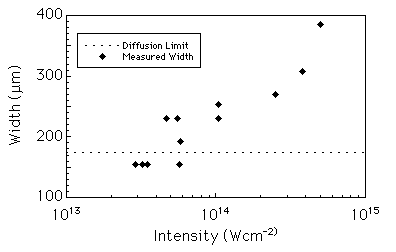
Fig.10 Width of the X-ray emitting region as a function
of the nominal intensity of the interaction beam focused on an Al plasma.
The plasma heating intensity was approximately Å4´1013 W/cm2
on each side of the target. The horizontal dashed line indicates the limit
set by the thermal diffusion length (175 µm) calculated in our experimental
conditions.
On the other hand, it is well known that, in the case of a steady state
laser heating of underdense plasmas, the dependence of plasma temperature
upon laser intensity is very weak, being described by a power law with
exponent much smaller than one. Most of the energy absorbed by the plasma
goes into kinetic energy, i.e. expansion and, in any case, the rate at
which heat energy is diffused over the surrounding plasma is high enough
to prevent large temperature increase of the irradiated plasma. In other
words, the region of plasma irradiated by the interaction pulse effectively
exhibits a relatively high heat capacity.
On the other hand, as the laser intensity decreases, the width
of the X-ray emitting region stabilises between 150 um and 200 um. This
value is in good agreement with the value given above for the thermal diffusion
length (175 um). Therefore, in the low intensity regime, the width of the
X-ray region is mainly determined by classical thermal diffusion processes
and is therefore basically independent from the laser intensity, being
a function of hydrodynamic plasma parameters only.
6. CONCLUSION AND PERSPECTIVES
A combination of a simple X-ray imaging device based on the pin-hole technique,
coupled to a gated, proximity focused, MCP intensifier, has been demonstrated
to be an ideal method for performing multiple time-resolved X-ray imaging
of rapidly evolving laser-plasmas. The technique can be easily adapted
to various experimental configurations involving different target configuration
and size or alternative laser beam set-up, by simply changing the X-ray
filter and by arranging the geometry of the primary imaging device (the
pin-hole array) in order to fit the required spectral properties of the
image, as well as its resolution and magnification. In addition, the timing
of each frame can easily be varied by simply adjusting the length of the
cables that deliver the high voltage pulses to each sensitive area of the
detection unit. On the other hand, the number of the frames that can be
obtained can also be varied by rearranging the design of the detection
unit.
The experimental results presented here with a preliminary analysis
and discussion, show how time-resolved X-ray imaging can provide valuable
information of the physics of laser-plasmas, which can be directly compared
with the results of simple analytical models or with the predictions of
numerical simulations. Fundamental aspects of the physics of laser-plasma
interactions relevant to ICF studies including absorption processes and
electron heat transport mechanisms can be investigated. In fact, the absorption
length inferred from the X-ray images presented in this work was found
to be in good agreement with the classical theory of linear collisional
absorption. Furthermore, the thermal diffusion length estimated from the
data was found to be consistent with the description provided by the classical
thermal transport theory.
REFERENCES
[1]T. Afshar-rad,
L.A.Gizzi, M.Desselberger, F.Khattak, O.Willi, Phys. Rev. Lett. 68,
942 (1992)
[2] K.S.Budil,
T.S.Perry, P.M.Bell, J.D. Hares, P.L. Miller, T.A. Peyser, R. Wallace,
H. Louis, D.E. Smith, Rev. Sci. Instrum.
67, 485 (1996).
[3] L.
Wiza, Nuc. Instrum. and Methods
162, 587 (1979).
[4]O.
Willi in Laser-Plasma Interactions 4, Proceedings of the 35th Scottish
Universities' Summer School in Physics, Edited by M.B. Hooper, (1988).
[5]J.D.Kilkenny,
Laser Part. Beams 9, 49 (1991).
[6] D.K.
Bradley, P.M. Bell, O.L. Landen, J. D. Kilkenny, J. Oertel, Rev. Sci. Instrum.
66, 716 (1995).
[7]Kentech
Instruments Ltd. Hall Farm Workshops, Didcot (UK).
[8]R.W.Lee,
L.Whitten, R.E.Stout II, J. Quant. Spectr. Radiat. Trans. 32, 91
(1984).
[9]L.A.Gizzi,
Ph.D. Thesis, Imperial College of Science, Technology and Medicine, (1994)
.
[10]L.A.Gizzi,
D.Giulietti, A.Giulietti, T.Afshar-rad, V.Biancalana, P.Chessa, C.Danson,
E.Schifano, S.M.Viana, O.Willi, Phys. Rev. E 49, 5628 (1994).
[11]L.
Spitzer Jr., R. Harm, Phys. Rev.
89, 977 (1953).


![]() .
The transverse size of the X-ray region as shown in frame #3 is now approximately
150 um compared to the 200 um of frame #3 in Fig.7.
.
The transverse size of the X-ray region as shown in frame #3 is now approximately
150 um compared to the 200 um of frame #3 in Fig.7.

